Showing posts with label atmega 8535. Show all posts

April 07, 2012

varying scr firing angle with Avr microcontroller(Proteus simulation)

        Hi friends here is the post about changing SCR firing angle control with the help of AVR microcontroller.
        You might be aware of basics of firing angle and its variation.So in a basic Firing angle variation mechanism you will need two things:  
                                                           1)ZERO CROSSING DETECTION  
                                                           2)FIRING SCR  AT DIFFERENT ANGLE
          First stage Zero crossing with AVR is damn easy thing as avr hardware supports zero-crossing detection. that means you can detect zero of 230 VAC with directly avr microcontroller and no additional hardware.
you can refer Avr's official application note to know more about zero crossing by microcontroller itself!!!! (Huh!!!!  QUESTION: How can avr tolerate 230 volts directly?
Answer: 1M resistor limits the current and internal avr diodes are used like clamper circuit.... to convert 230 volts to 5 volts that is accessible by micro-controller.)


zero crossing detection and firing angle control with avr
Zero crossing in avr with internal diodes
             now once you are through with 230v detection and generating an interrupt with the help of zero crossing, you are good to go for varying firing angle of scr.


After varying the firing angle you will be able to see the pulses as shown below


proteus scr firing angle
Firing angle


here is the source code to generate scr triggering pulse from microcontroller and varying it with 2 push buttons(i.e. increase or decrease firing angle) push buttons are connected to  PINA.6 and PINA.7 additionally a stop button is also used to stop SCR firing..
Stop button is connected to PINA.3 Here is the source code for that --------------------------------------------------------------------------------------------
#include"avr/io.h"
#include"delay.h" 
unsigned char stop=0;
unsigned long scrangle=0;
ISR(INT0_vect)
{
if (stop==0)
        {
        delayus(scrangle);
        PORTB=PORTB|0x01;
        delayus(1000);
        PORTB=PORTB &0xFE;
        }
}  void main()
   
     SREG=SREG|0x80;        //global interrupt enable  
     PORTA=0xFF;            // configuering the PORTA in pullup mode.
     DDRA=0x00;                // Port A data direction configuration as input port. 
    MCUCR=MCUCR|0x01;        // logic change  in pin generates an interrupt(hardware interrupt 0) 
    GICR=GICR|0x40;            //enable the interrupt 0 
        if((PINA & 0x80)==0x00)  //decrease firing angle
        {
            if(scrangle>0)
            {
                scrangle=scrangle-100;
            }
        }
        if ((PINA & 0x40)==0x00)    //increase firing angle
         {
            if(scrangle<8000)
            {
                scrangle=scrangle+100;
            }
           
         }
        if((PINA & 0x08)==0x00)    //reset pin to stop
            {
            stop=1;
            }
     } 
} 
 ------------------------------------------------------------------------------------------------------
Here is the output waveforms you can see a pulse generated by micro-controller on zero-crossing detection..

zero crossing with micro-controller
Pulse generated by Micro-controller on zero-crossing.


Thats all I have to say.
But remember some points guys...

1)You are playing with Mains power supply so be very very careful.
2)Ground of microcontroller and mains are not good isolated.
3)This is only pulse generation by microcontroller if you need to apply this pulse to SCR you have to put some conditioning circuit.
Read more ...

March 11, 2012

IRF 640 & IRF Z44 triggering with AVR Microcontroller(Proteus Simulation)

I am working with power inverter design for final year project. I am using AVR atmega 8535 microcontroller for triggering MOSFET and PWM control.

I started working with IRF 640 Mosfet (That was the only available to nearer electronics shop at that time).

An optocoupler IC MCT2E is used for isolation between low voltage side(Microcontroller) to the high voltage side (MOSFET side load). It is always suggested to do so.

Here is the circuit configuration i have used to trigger MOSFET. 
optocoupler irf640 triggering with power mosfet
Power mosfet trigger with avr microcontroller by optocoupler in proteus

But while working with optocoupler it is always desirable to use datasheet very carefully. That was the problem with my earlier configuration I blindly put 330 ohm to input side of optocoupler (obviously for current limiting) as we do with normal LED. so I was having 100 uS delay on output side. But that was not proper configuration  according to the MCT2E datasheet. So after studying datasheet and test circuit given in it i come to know that it is 47 ohm is perfect value. And I was able to reduce the delay upto 5 uS(that was desirable to our case).


Then after some successful experiments I replaced IRF 640 with IRF Z44 which was having higher current carrying capacity than the IRF 640.There would be no change in driving circuit as the both MOSFET are pin to pin compatible and gate pulse requirement for both of them is same.

I have tested the circuit in simulations and hardware.

here is the Proteus ISIS simulation of MOSFET triggering 

 
Read more ...

February 14, 2012

AVR Software UART (Proteus simulation)

What is software UART?

             Software UART is the method of creating serial asynchronous transmission and reception  pins on almost every pins of your avr microcontroller.

Why Software UART?

              Whenever you are in need of more UART pins than given on your microcontroller chip you can use software UART. You can configure every I/O pin as serial transmission and reception pin.

Demo of software UART:

          Here in this demo I have created one software UART on each i.e. on PORTA.1 , PORTB.1 , PORTC.1, and one hardware UART on PORTD.1


            when you run the demo code given below all three software uart and one hardware uart will start working as shown below.


I have used BASCOM for AVR to program my avr-8535 microcontroller.

Here is source code for AVR 8535 and simulation files of Proteus ISIS.
Read more ...

October 21, 2011

Bidirectional Motor With 1 Pin of Microcontroller (Proteus Simulation)


How to drive a motor with a single pin of microcontroller?
A tough question but I have got the answer and the answer is “H-bridge connection”
Now you may be think that normally all the motors are driven by H-bridge connection and it would be even easier to drive them with motor driver IC so what is new here?
Here is a new configuration that can drive entire H-bridge with a single pin of micro controller, but for that you have to insert some extra hardware in that
A simple configuration is given below…
Bidirection Motor control


                    You can change the frequency of pulse to change the speed of motor and you can also vary PWM to generate asymmetric motor drive, and this entire thing at the cost of just one micro controller pin

                    we can easily stop the motor by tri-stating the microcontroller pin by just two simple lines of code that is 

   DDRB=0x00;
   PORTB=0X00;

                    But when working with Proteus you realize that some things are out of your control, i mean to say that when port pin is not connected to H-bridge it is tri stated properly but as soon as you connect it to bridge your tri-stated output is magically "converted" into ground that's why i could not include "stop motor" action in this demo.
                    Here I have just used a simple program to generate a 2 second delay and run motor in clockwise or anticlockwise.
                   The program is written for Atmega 8535(crystal frequency=16Mhz ; I am using earlier made header file)
  
#include"avr/io.h"                     
#include "delay.h"

void main(void)
 {        
            DDRB=0x08;                                   // Port B data direction declaration as output.
            PORTB=0X00;
            while(1)                               //This is for the infinity loop.
            {         
             PORTB=0X08;
             delayms(2000);                //2 second delay
             PORTB=0X00;
             delayms(2000);                //2 second delay
            }
}

You can download source code file for this project and ISIS Proteus design HERE.
Read more ...

October 20, 2011

Password protect your microcontroller

Untitled Document
Hello friends, a good idea of privileging the execution of main program of microcontroller came in my mind after watching a Si-Fi movie……and I did it………

Password protecting your microcontroller is one of the coolest things you can do with it……


I created a routine that reads 5 keystrokes and then checks weather the inserted password is right or not.
the micro controller here used is  Atmega 8535
 Not discussing much more about logic, here is the program
----------------------------------------------------------------------------------------------
void main()

{
  unsigned char a,b,c,d,e;           
  DDRA=0x00;
  PORTA=0xff;
                               //ask for password

 while(1)
 {
  lcd_init();
  lcd_string("Enter a 5 digit");
  lcd_gotoxy(1,0);
  lcd_string("Password:");
                                             //read password
  while(PINA==0xff);                    //if all keys open stay here
  a=PINA;
  delayms(200);
    lcd_gotoxy(1,0);
            lcd_string("Password:*");
            while((PINA&0xf0)!=0xf0);      //wait to release the key
 while(PINA==0xff);        
             b=PINA;
  delayms(200);
    lcd_gotoxy(1,0);
            lcd_string("Password:**");
            while((PINA&0xf0)!=0xf0);     //wait to release the key
 while(PINA==0xff);        
             c=PINA;
  delayms(200);
    lcd_gotoxy(1,0);
            lcd_string("Password:***");
             while((PINA&0xf0)!=0xf0);   //wait to release the key
 while(PINA==0xff);        
 d=PINA;
  delayms(200);
    lcd_gotoxy(1,0);
            lcd_string("Password:****");
            while((PINA&0xf0)!=0xf0);   //wait to release the key
 while(PINA==0xff);        
             e=PINA;
  delayms(200);
    lcd_gotoxy(1,0);
            lcd_string("Password:*****");   //wait to release the key


                                   //checking the password
  if(a==0xef)
  {
  if(b==0xdf)
            {
            if(c==0xbf)
               {if(d==0x7f)
                        {
                                    if(e==0xef)
                                    {
                                    lcd_init();
                                    lcd_string("Welcome");
                                    goto wait;
                                    }
                                    else
                                    {
                                                            lcd_init();
                                                            lcd_string("Invalid password!!");
                                                            delayms(2000);
                                    }
                        }
                        else
                        {
                                                lcd_init();
                                                lcd_string("Invalid password!!");
                                                delayms(2000);
                        }

            }
            else
            {
            lcd_init();
            lcd_string("Invalid password!!");
            delayms(2000);
            }
            }
   else
  {
  lcd_init();
  lcd_string("Invalid password!!");
  delayms(2000);
  }
  }
 else
  {
  lcd_init();
  lcd_string("Invalid password!!");

  delayms(2000);

  }
  }
  wait:while(1);                      
            }

----------------------------------------------------------------------------------------------


and no post is completed without a video,


leave a comment if you want to ask any thing related to programming.

:)
Read more ...

October 16, 2011

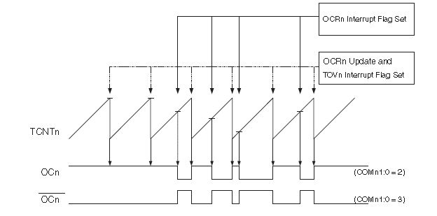
Fast Pwm mode of avr timers


Hello folks, I once needed to generate PWM wave  in my project related to power inverter design, I had to generate PWM waveforms according to the potentiometer varied by the user.
For that first method which I adopted was discussed earlier post but now here is another sophisticated method which I came across while studying the datasheet of mine microcontroller (mine favorite Atmega 8535).I came across the PWM modes given inbuilt in AVR series.
There are three modes of generating PWM in Atmega8535
1)Clear timer on compare(CTC) mode.

2)fast PWM mode

3)Phase correct PWM mode.


You can select any of them according to your requirement as in my requirement I had to select fast PWM mode.

Here are the steps given to configure your timer in fast PWM mode…..

Step 1) set Port in output mode
                                As the PWM generated would be given to output pin first of all that pin must be taken to output mode.the PIN where PWM is to be generated depends on the timer which you use to generate PWM. The pin OCn would be your output pin if you are using Timer-n. you can find the location of pin from datasheet.

Step 2) Set TCCRn register
                                You have to configure your timer in prescaler mode, OCn pin in inverting or non-inverting mode, selection of PWM mode etc. can be configured just within one register.
Step 3) Change the value of OCRn register in run time to generate PWM whatever you want…
Now your timer is configured to work with PWM mode
As I discussed earlier if we want to have a variable resistor  that can generate variable PWM for that we have to access ADC given in Atmega.

For adc initialization you have to do following steps
Step 1)  Initialize adc
                                You can do it by ADCSRA register you have to Enable, prescale and set interrupt .
Step 2)give ADC channel no
                                This no is given in ADMUX register.
Step 3)start conversion
                                Setting ADSC bit in ADCSRA register will do this thing.
Step 4) give it some time to convert and then read the result from ADCH and ADCL register.


Now you are done to interface your ADC with Timer

A sample code which I had used is given below.
#include<avr/io.h>
#include<delay.h>
void adc_init()
 {
ADCSRA=0X86;                              //ADC enable, ADC interrupt enable, set prescaller to 64
 }
 unsigned char getdata(unsigned char chno)        
  {
    ADMUX=0X60;                                       //right align the ADC result
    ADMUX|=chno;                                      //select the ADC channel
    ADCSRA|=0X40;                                     //start ADC convertion
    delayms(1);                                             //give some time delay to complit the ADC convertion
            return ADCH;
  }

void main()
{          unsigned char pot=0;
            adc_init();
             SREG=SREG|0x80;//global interrupt enable
             DDRB=0XFF;          //set data direction as output
TCCR0=TCCR0|0x7A;       //fast pwm,inverting mode,8 prescaler
while(1)
             {
             delayms(10);
             OCR0= getdata(0);          //read value from pot to OCR0
            }
}

Link to .zip file containing source code and Proteus ISIS design is this.
and datasheet of Atmega 8535 can be found from here.


if any question  then you can post a comment. 

Read more ...
Related Posts Plugin for WordPress, Blogger...