October 22, 2011

DAC by PWM (Proteus Design)

As i was reading a book "Embedded systems" by Rajkamal I found some thing interesting on Page 15 that was "DAC using PWM". Then I tried to implement it on my own as it was an interesting idea to generate Analog voltage from only one pin of micro controller.


so here is another post demonstrating the magic of AVR Atmega 8535.

Normally for DAC we have to use 8-pin and it is always good to use less pins.

Here we have to use only one pin to generate PWM and then Integrate the wave to make analog output.I have used an op-amp integrator(low-pass filter) .

I have used program made by me earlier that generates PWM according to potentiometer varied.
Just adding a next stage to it i gave that pwm pulse to an Op-amp based integrator.
Here is the rar file given which contains Proteus ISIS design file and source code to generate PWM in AVR atmega 8535.

The design is made for test purpose only to check the concepts, hardware is not built and tested  so enough care must be taken before converting this design file to actual hardware.

Hope the new concept is good for implementing.

:)
Read more ...

October 21, 2011

Bidirectional Motor With 1 Pin of Microcontroller (Proteus Simulation)


How to drive a motor with a single pin of microcontroller?
A tough question but I have got the answer and the answer is “H-bridge connection”
Now you may be think that normally all the motors are driven by H-bridge connection and it would be even easier to drive them with motor driver IC so what is new here?
Here is a new configuration that can drive entire H-bridge with a single pin of micro controller, but for that you have to insert some extra hardware in that
A simple configuration is given below…
Bidirection Motor control


                    You can change the frequency of pulse to change the speed of motor and you can also vary PWM to generate asymmetric motor drive, and this entire thing at the cost of just one micro controller pin

                    we can easily stop the motor by tri-stating the microcontroller pin by just two simple lines of code that is 

   DDRB=0x00;
   PORTB=0X00;

                    But when working with Proteus you realize that some things are out of your control, i mean to say that when port pin is not connected to H-bridge it is tri stated properly but as soon as you connect it to bridge your tri-stated output is magically "converted" into ground that's why i could not include "stop motor" action in this demo.
                    Here I have just used a simple program to generate a 2 second delay and run motor in clockwise or anticlockwise.
                   The program is written for Atmega 8535(crystal frequency=16Mhz ; I am using earlier made header file)
  
#include"avr/io.h"                     
#include "delay.h"

void main(void)
 {        
            DDRB=0x08;                                   // Port B data direction declaration as output.
            PORTB=0X00;
            while(1)                               //This is for the infinity loop.
            {         
             PORTB=0X08;
             delayms(2000);                //2 second delay
             PORTB=0X00;
             delayms(2000);                //2 second delay
            }
}

You can download source code file for this project and ISIS Proteus design HERE.
Read more ...

October 20, 2011

Password protect your microcontroller

Untitled Document
Hello friends, a good idea of privileging the execution of main program of microcontroller came in my mind after watching a Si-Fi movie……and I did it………

Password protecting your microcontroller is one of the coolest things you can do with it……


I created a routine that reads 5 keystrokes and then checks weather the inserted password is right or not.
the micro controller here used is  Atmega 8535
 Not discussing much more about logic, here is the program
----------------------------------------------------------------------------------------------
void main()

{
  unsigned char a,b,c,d,e;           
  DDRA=0x00;
  PORTA=0xff;
                               //ask for password

 while(1)
 {
  lcd_init();
  lcd_string("Enter a 5 digit");
  lcd_gotoxy(1,0);
  lcd_string("Password:");
                                             //read password
  while(PINA==0xff);                    //if all keys open stay here
  a=PINA;
  delayms(200);
    lcd_gotoxy(1,0);
            lcd_string("Password:*");
            while((PINA&0xf0)!=0xf0);      //wait to release the key
 while(PINA==0xff);        
             b=PINA;
  delayms(200);
    lcd_gotoxy(1,0);
            lcd_string("Password:**");
            while((PINA&0xf0)!=0xf0);     //wait to release the key
 while(PINA==0xff);        
             c=PINA;
  delayms(200);
    lcd_gotoxy(1,0);
            lcd_string("Password:***");
             while((PINA&0xf0)!=0xf0);   //wait to release the key
 while(PINA==0xff);        
 d=PINA;
  delayms(200);
    lcd_gotoxy(1,0);
            lcd_string("Password:****");
            while((PINA&0xf0)!=0xf0);   //wait to release the key
 while(PINA==0xff);        
             e=PINA;
  delayms(200);
    lcd_gotoxy(1,0);
            lcd_string("Password:*****");   //wait to release the key


                                   //checking the password
  if(a==0xef)
  {
  if(b==0xdf)
            {
            if(c==0xbf)
               {if(d==0x7f)
                        {
                                    if(e==0xef)
                                    {
                                    lcd_init();
                                    lcd_string("Welcome");
                                    goto wait;
                                    }
                                    else
                                    {
                                                            lcd_init();
                                                            lcd_string("Invalid password!!");
                                                            delayms(2000);
                                    }
                        }
                        else
                        {
                                                lcd_init();
                                                lcd_string("Invalid password!!");
                                                delayms(2000);
                        }

            }
            else
            {
            lcd_init();
            lcd_string("Invalid password!!");
            delayms(2000);
            }
            }
   else
  {
  lcd_init();
  lcd_string("Invalid password!!");
  delayms(2000);
  }
  }
 else
  {
  lcd_init();
  lcd_string("Invalid password!!");

  delayms(2000);

  }
  }
  wait:while(1);                      
            }

----------------------------------------------------------------------------------------------


and no post is completed without a video,


leave a comment if you want to ask any thing related to programming.

:)
Read more ...

October 16, 2011

Fast Pwm mode of avr timers


Hello folks, I once needed to generate PWM wave  in my project related to power inverter design, I had to generate PWM waveforms according to the potentiometer varied by the user.
For that first method which I adopted was discussed earlier post but now here is another sophisticated method which I came across while studying the datasheet of mine microcontroller (mine favorite Atmega 8535).I came across the PWM modes given inbuilt in AVR series.
There are three modes of generating PWM in Atmega8535
1)Clear timer on compare(CTC) mode.
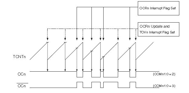
2)fast PWM mode

3)Phase correct PWM mode.


You can select any of them according to your requirement as in my requirement I had to select fast PWM mode.

Here are the steps given to configure your timer in fast PWM mode…..

Step 1) set Port in output mode
                                As the PWM generated would be given to output pin first of all that pin must be taken to output mode.the PIN where PWM is to be generated depends on the timer which you use to generate PWM. The pin OCn would be your output pin if you are using Timer-n. you can find the location of pin from datasheet.

Step 2) Set TCCRn register
                                You have to configure your timer in prescaler mode, OCn pin in inverting or non-inverting mode, selection of PWM mode etc. can be configured just within one register.
Step 3) Change the value of OCRn register in run time to generate PWM whatever you want…
Now your timer is configured to work with PWM mode
As I discussed earlier if we want to have a variable resistor  that can generate variable PWM for that we have to access ADC given in Atmega.

For adc initialization you have to do following steps
Step 1)  Initialize adc
                                You can do it by ADCSRA register you have to Enable, prescale and set interrupt .
Step 2)give ADC channel no
                                This no is given in ADMUX register.
Step 3)start conversion
                                Setting ADSC bit in ADCSRA register will do this thing.
Step 4) give it some time to convert and then read the result from ADCH and ADCL register.


Now you are done to interface your ADC with Timer

A sample code which I had used is given below.
#include<avr/io.h>
#include<delay.h>
void adc_init()
 {
ADCSRA=0X86;                              //ADC enable, ADC interrupt enable, set prescaller to 64
 }
 unsigned char getdata(unsigned char chno)        
  {
    ADMUX=0X60;                                       //right align the ADC result
    ADMUX|=chno;                                      //select the ADC channel
    ADCSRA|=0X40;                                     //start ADC convertion
    delayms(1);                                             //give some time delay to complit the ADC convertion
            return ADCH;
  }

void main()
{          unsigned char pot=0;
            adc_init();
             SREG=SREG|0x80;//global interrupt enable
             DDRB=0XFF;          //set data direction as output
TCCR0=TCCR0|0x7A;       //fast pwm,inverting mode,8 prescaler
while(1)
             {
             delayms(10);
             OCR0= getdata(0);          //read value from pot to OCR0
            }
}

Link to .zip file containing source code and Proteus ISIS design is this.
and datasheet of Atmega 8535 can be found from here.


if any question  then you can post a comment. 

Read more ...

October 10, 2011

Custom character and animation on LCD


Hello friends I have been very fascinated about the custom character generation on normal (16x2) LCD
So I decided to have some hands on about it. I started reading about it on net and finding data about CGRAM.
I came across many good websites they are listed at the end of the post..
There are mainly two RAMs in our LCD display
1)DDRAM-you put the ASCII value and it is displayed on the screen (normally everybody is aware with it)
2)CGRAM-discussed below in detail  
                CGRAM is 64 Byte ram we can use it to make 8 custom characters.so this is clear that each character consist 8 bytes now let us start generating a custom character.


Each block we see in our LCD is 5x8 pixels(5 columns & 8 rows) we can configure lcd row by row as shown in the figure thus we get 8 bytes for one pixel.
We can make 8 characters in CGRAM so after obtaining the values of each row just load it to CGRAM .To do so you have to point starting address of RAM you can take help of the below given able you have to do  0x40+(CGRAM address)once a byte is written on the RAM location then you need not to point the next data then the pointer is incremented by itself.


Now if you have constructed your character in CGRAM how would you display it ?
This is the question puzzled me the most. I’ll try to explain in easy words .once you have created your character in any location in CGRAM (say 1st location=0x40 to 0x48)   and you want to display it in any location (say 1st row 6th column=0x86)then point to 0x86 by using    “lcd_cmd(0x86)” and write ASCII value zero  (‘0’)(this is the equivalent value of CGRAM 1st location)there you can see the table below to get the ASCII values of   Characters generated in CGRAM.


So you are now done with all the basics of generating a custom character you can generate a character independently or with the help of two or more blocks as shown below.

I tried to generate the rupee symbol on LCD. But first I generated it on paper to get some better idea.  
So here are some demos of what you can do…..

 Indian Rupee symbol (Designer: kishan. keyur)….


A car( Designer: Preet)……


now thats not all
do it sound cool then look at the video you can see the animation done in 16x2 lcd....


further more you can develop interactive game with the help of this experience.
links:
the LCD which i used

hope you enjoyed the post as i did...


:)


Read more ...
Related Posts Plugin for WordPress, Blogger...