December 26, 2011

Displaying string on Dot Matrix Display(Proteus simulation)

In earlier posts we have discussed about how to display alphanumeric characters on a single block of 5x7 dot matrix display.  but now it is time to move on to display characters on a series of blocks. basic concept remains same.  Only two things are new here
  1. Buffer with tristated output (74 LS 541)
  2. De-multiplexer(74 LS 138)
Buffers here are used to isolate other blocks while accessing a single block.
Let us say we want to dispaly 'Y' on 3rd block so at that time we must not disturb other blocks so we have tristated(in rough term disconnected ) them to prevent from any changes.


De-multiplexers are used to decode address of the destination block. Assume we are having 30 blocks to display in that case we can't give separate enable pin to each Buffer that's why if we are having a 5to32 demultiplexer we can address up to 32 blocks with help of only 5 pins of microcontroller.
Here in my design i only wanted to display 5 Characters simultaneously so i used 3to8 demultiplexer(decoder).


dot matrix display proteus avr
5x7 Dot matrix display in proteus


by inserting some decoding mechanism in our program and using earlier made header file we are all set to display a message 'KEYUR' on the blocks. the program is as shown below


#include"avr/io.h"
#include"delay.h"

#include"dotmatrix.h"
void main()
{

            DDRA=0xFF;          
            DDRB=0xFF;
            DDRC=0xFF;
            while(1)
            {
            PORTB=0;    //select first block
            display('k',1);
            PORTB=1;    //select second block
            display('e',1);
            PORTB=2;    //select third block
            display('y',1);
            PORTB=3;    //select fourth block
            display('u',1);
            PORTB=4;    //select fifth block
            display('r',1);
          
            }
          
}


we can further minimize the program by making a function to display message on series of displays.

final output may look like this
string on 5x7 dot matrix display
A creative imagination you will not see this in software
here is the source code, header file, Proteus ISIS design file and .hex file for AVR Atmega 8535 Microcontroller.

      I figured it out that this source code and circuit diagram is not only for a string displaying on dot-matrix.But if you want to design NxNxN (3X3X3,8X8X8,anything ) cube of LEDs to display some fancy patterns this circuit design and coding will be like a base guide for you.

  That cube display will be more attractive than this one displayed above but i found above one more commercial to make.


1           2            3
Read more ...

Creating Characters on Dot matrix display (Proteus Simulation)

In earlier post we have seen how to make a single LED,a Row  or a Column ON. But that's not enough when we want to generate a character like 'K' on a display so what we have to do for that?


Here comes a principle from physics called "Perception of eye" I hope all have studied about that in high school so not discussing more about that in detail just keep in mind that if we constantly change our ON LED we can make an image like any character on human eye.


so

 +

 +

 +

 +


  =

alphanumeric character in dot matrix display
alphanumeric character on dot matrix


this is the magic of perception of eye principle if you will repeat above 5 images at enough faster rate you will be able to see a  'K ' character.


Doing this with microcontroller is damn easy thing.

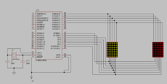
just try following code in your AVR 8535 microcontroller to see the character being displayed.


//program to display K on dot matrix display

#include"avr/io.h"
#include "delay.h"


void main(void)
 {  
    DDRA=0xFF;            // Port A data direction declaration as out put.
    DDRC=0xFF;          
// Port C data direction declaration as out put.
    while(1)      
    {
    PORTA=0b00000001;            //column 1
    PORTC=0b10000000;          
    delayms(1);
    PORTA=0b00000010;            //column 2
    PORTC=0b11110111;
    delayms(1);
    PORTA=0b00000100;            //column 3
    PORTC=0b11101011;
    delayms(1);
    PORTA=0b00001000;            //column 4
    PORTC=0b11011101;
    delayms(1);
    PORTA=0b00010000;            //column 3
    PORTC=0b10111110;
    delayms(1);
    delayms(1000);
    }
  
}

the circuit diagram for above program is given below...


with this all you can make all your  characters and display them on dot matrix display.


Once you are through with all your characters making you can group them in a standard header file to use later.you can read my earlier post  "how to make a header file?" for the help.

this is good if you want to display something on a single block of dot matrix display but what if you want to display a message such as "KEYUR" on a series of blocks????

1    2      3
Read more ...

Dotmatrix LED(5x7)

I was always fascinated to see the large boards made of  red LEDs and i always thought that some day i will make it i hope you also have same thoughts that's why you are on this page, right?
So let us start with what is a basic dot matrix LED connection?
It is connections of LED in such a way that more LEDs can be accessed by less no. of micro controller pins.


as you can see in figure.


Internally, the LEDs are organized in a matrix. Here's a 5x7 display internal wiring (requires a minimum of 13 pins, likely to be shipped in a 14 pins package).
so you can access 35 LED with just 13 pins of microcontroller isn't it a great deal?

Now got enough information about dot matrix so let us start with how to use them?

Basically you can turn on those LEDs to which you supply proper forward biasing all the game starts from here.
see in the figure if you want to make left top corner LED(we want to turn on only one LED right now note that) you have to give a high to 1 pin and a low to A pin.
but if you observe something you will come to know that if we apply low to rest of the B to G pins whole first column  will glow up but that's not we want. so we have to give A=low and B-G=high to make a LED on.

Hey wait did you again observe something? let me tell you that if we have A=low and B-G=high that's fine but what about the pins 1-5? so if we have 1-5=high and A=low and B-G=high we will get the first row on because of the connections so now what to do ?
we can again  change our configurations to 1=high, 2-5=low, A=high, B-G=low.

huh, so is that enough to turn on single LED on your display..?

yes that's all you have to do to make different LEDs on.
Now you have the power to turn on any desired LED of 5x7 matrix.


Are you happy with this thing?
if yes then what about displaying characters on matrix.


1      2        3

Read more ...

December 25, 2011

How to learn PLC?

Hello, friends I have been so much fascinated about PLC  since I have read about it.
Here is a best book which you can use to study PLC (which I am using) this is a great book which can tech PLC from scratch. It is as easy as reading a book you can use Nationa Instruments Multisim this is the best software for simulating PLC(as far as I have found)


here are some pics. of basic PLC circuits made by me
seal in circuit


oscilations
Read more ...
Related Posts Plugin for WordPress, Blogger...