December 26, 2012

Sine wave generating from PIC

Hello friends,

To do sinusoidal modulation you need sine wave which can be compared with high frequency carrier(triangular waves). And i was also about to generate Sine modulation so i needed to do this.


      You can generate by calculating sine values at run time also but that is time consuming and keeps your microcontroller busy with calculations only, so I suggest you to make a look up table  and recall the value at run time from there.

      So here is what I have done its a simple task just have a look at the code,....

///////////////////////////////////////////////////////////
#include "pic .h
#include "htc .h"
#define _XTAL_FREQ 4000000

const unsigned char wave[181] ={128,132,137,141,146,150,155,159,163,168,172,176,180,184,188,192,196,200,203,207,210
,214,217,220,223,226,229,232,234,237,239,241,243,245,247,248,250,251,252,253,254,254,
255,255,255,255,255,255,255,255,254,253,252,251,250,248,247,245,243,241,239,237,234,
232,229,226,223,220,217,214,210,207,203,200,196,192,188,184,180,176,172,168,163,
159,155,150,146,141,137,132,128,124,119,115,110,106,101,97,93,88,84,80,76,72,68,64,
60,56,53,49,46,42,39,36,33,30,27,24,22,19,17,15,13,11,9,8,6,5,4,3,2,1,1,0,0,0,0,0,1
,1,2,3,4,5,6,8,9,11,13,15,17,19,22,24,27,30,33,36,39,42,46,49,53,56,60,64,68,72,76,
80,84,88,93,97,101,106,110,115,119,124,128};

int main(void)
{
TRISD = 0x00;
unsigned char i;

for(i=0;i<181 ;i++) {
PORTD = wave[i];
__delay_us(79);
}

return 0;
}

///////////////////////////////////////////////////////////

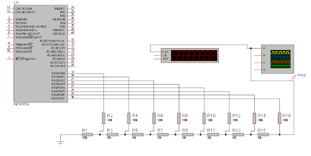
 But,here instead of using normal DAC to generate sine wave I have here used R-2R ladder(no specific reason).
Here is the schematic.

R-2R ladder in proteus generating sine wave for sine modulation

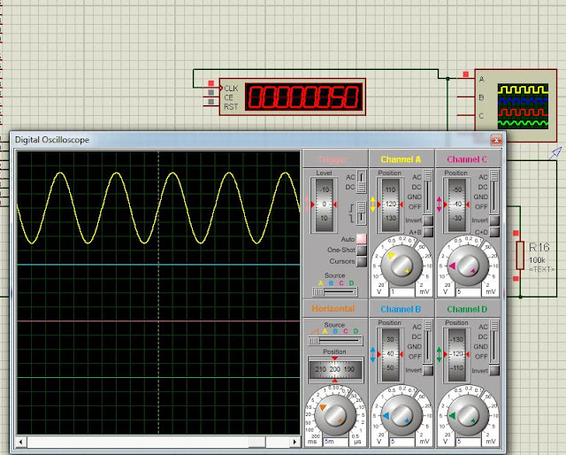
Here VSM Timer counter is used to measure the frequency generated by R-2R DAC. 


The output of the circuit is as shown below..

Sine wave and vsm counter in proteus

if you want to make frequency variable just keep a variable in delay and update it by any key..... 


For more Proteus projects  click here.
Read more ...

Sinusoidal modulation in PIC

Hello Friends,

Many of the readers are asking for sinusoidal modulation with pic microcontrolle. So here is the answer....

1)Read my previous post about sine wave modulation.

2)Now you need  Sine wave of 50Hz to generate reference for modulation.Read this post about generating Sinusoidal waveforms with PIC. (you can generate sine wave from any microcontroller by using this method.)

3)Create a triangle wave either from microcontroller or 555 timer IC.

sine pwm modulation in pic
4)You are done ......


You can see other AVR Projects HERE.


Read more ...

December 05, 2012

Graphical programming including VHDL with code generation

Hello friends i was always fascinated about programming graphically so we don't need to write any code(that saves your lot energy, don't consider me lazy!!!!).

Here is the answer of

How to do VHDL programming graphically?

step1) Open NI- Multisim
ni-multisim


step 2) go to place menu and select "New PLD Sub circuit"


step 3) then a PLD wizard will open select "Create empty PLD" and in subsequent steps select the name of circuit and operating voltage of the processor ( it has nothing to do with code generation but only useful for simulation in Multisim)

PLD wizard

step 4) click on the PLD setting Button

pld setting

step 5) you will be asked  for input, output and bi-directional pins in this menu


select_io_pins


step 6) now make whatever circuit you want to make(time to  have fun!!!)...

gate_schematic


step 7)  Click on PLD topology check


step 8) if there is no error in your topology you can export the VHDL code


step 9) finally your VHDL code is ready to be saved save it whenever you want  and have fun.

step 10)  Go to main circuit and build some circuit around your PLD to simulate


 Step 11) Don't forget to leave a comment here.....!!!!


"LET THY BE FREE FROM TEXTUAL PROGRAMMING"

                                                                          -Keyur


Read more ...

November 28, 2012

Inrush Current in single phase rectifier

Hello friends, this post is about simple full bridge rectifier.

As, we know that un-rectified output from single phase full bridge rectifier is some what like shown below.
full bridge rectifier


But we or clearly speaking our devices don't like this type of voltage so what we do is simply put a capacitor at the output of rectifier called the "Filter capacitor" this capacitor works fine for smoothing the voltage output as shown in below figure.

full bridge rectifier capacitor filter


it is taught in school or college that as we increase the capacitor or decrease the capacitor value the smoothness changes.

By increasing the capacitor..
full bridge rectifier capacitor filter
  By decreasing the capacitor...
full bridge rectifier capacitor filter


Now some smart ass would say that lets make the capacitor value infinity and we get perfect DC Output from the rectifier.

Huh that's nice, if we ignore initial current flowing from the source to the capacitor.
now have a look at the value of initial current flowing from source to charge the capacitor in initial time because at the start time the capacitor would be fully discharged....

When the capacitor is small

inrush current because of rectifier filter

When capacitor is huge
inrush current because of rectifier filter

Now that's a problem huh!!!!!

so what to do to solve the problem?
There is a magical device called NTC (Negative Temperature Coefficient) resistor
as the name suggest when resistor becomes hot it's resistance decreases.
Initially it helps it softly charge the capacitor but when current passes from it it becomes hot and resistance decreases so that there is not any drop across the resistor...
inrush current supressor


By increasing the value of soft-charge resistor we are able to charge capacitor even slowly.... as shown in below figure.

soft charge of capacitor in rectifier
this can help you protect your equipments and fuses......    ;)


if any problem or suggestion please feel free to post your comments....
Read more ...

November 08, 2012

Single Phase sine wave inverter (PSIM Simmulation)

>>Hi friends many of readers asked for sinusoidal modulation and sine wave inverter.

>>Here is the PSIM Simulation of single phase sine wave inverter.

>>Here a sine wave Source of 50Hz, 2V offset and 4V Peak to peak  is modulated by triangular wave of 4V.


Sine PWM inverter
>>You can see this in above image.


Now this signals are applied to full bridge inverter as shown in below figure.

Schematic of sinewave single phase inverter


Output of bridge if applied to inductive load it will generate almost sinusoidal waveforms current output is observed this can be seen in below waveform.

Sine modulated inverter

here is the PSIM simulation file.
Read more ...

September 07, 2012

Induction heating simulation

Hello friends this post is about "induction heating" project on which i was working in final year.
                  I have already post about PWM pulses generation and MOSFET triggering with microcontroller which are two important aspects I found out during my final year project.
                  Here is the Pwm scheme which i have used to generate pulses.


pwm pulses mosfet bridge induction heating
Triangular wave and two reference levels


  • First of all I generated a triangular wave (inside microcontroller) this is called Phase correct PWM in AVR microcontroller.


pwm pulses with guard band with microcontroller
Pwm pulses with guard band

  • Then I generated two levels with which I want to compare my triangular wave... which leads to the following type of pulses with guard band.
Gate pulse logic
  •  here is the logic which i used to generate gate pulse.

  • these pulses are then applied to MOSFET as discussed in this post via  opto-couplers to this bridge configuration
inverter bridge circuit
Inverter bridge


  • with inductor and capacitor series resonant circuit as  load I got this current output waveform from the load.
inverter with inductive and capacitive load
Current waveforms of inductor

Questions and suggestions are always welcomed in comment box.......so feel free to comment.
Read more ...

April 20, 2012

Frequency control of inverter (Proteus simulation)

Hello folks,
       Here is the post about Frequency control of Inverter with Avr microcontroller.
There are two method to control output power of inverter they are
1)PWM control (read this post)
2)Frequency control

   Que:     "How power of inverter is controlled by frequency control?"
    Ans:  This method is for series or parallel resonant circuit connected as load to the inverter.
resonance curve graph plot series parallel
LC Resonance curve
as you can see in the graph that maximum current flows at resonance frequency. if the frequency is above or below that the current decreases and power can be controlled with variation in frequency.

so, now you know why you need frequency control of inverter for power control in L-C tank circuits.
But, how to do that with AVR?
We can use timers in AVR microcontroller  to produce frequency whatever we want.(sounds so easy, yes it is so easy!!!)
But,that's not all we just don't have to make a pulse from microcontroller we have to make two non-overlapping pulses for full bridge inverter
H-bridge configuration
Full bridge full controlled inverter
as you can see from the fig we have to trigger S1 and S4 at same time and S2 and S3 at same time but pulses P1(for S1 and S4) and P2(S2and S3) should be non overlapping!!!

that has been taken care in the programming. We have inserted approx 6uS guard time for two pulses.

this is the specifications of below written BASCOM-code
1)Guard time of 6uS
2)Frequency display on LCD
3)2.1kHz to 10.8kHz frequency range
--------------------------------------------------------------------------------------------------------
'author:keyuracharya.blogspot.com
$regfile = "m8535.dat"                                      ' specify the used micro

$crystal = 16000000                                         ' used crystal frequency

'$baud = 9600                                                ' use baud rate

'$hwstack = 32                                               ' default use 32 for the hardware stack

'$swstack = 10                                               ' default use 10 for the SW stack

'$framesize = 40


Config Lcdpin = Pin , Db4 = Portc.4 , Db5 = Portc.5 , Db6 = Portc.6 , Db7 = Portc.7 , E = Portc.2 , Rs = Portc.0
Config Lcd = 16 * 2
Cursor Off

Dim Mybit1 As Bit
Dim Timer1_val As Byte
Dim Freq As Single
Dim T1 As Integer
Dim Diff As Byte
Dim S1 As String * 16


Mybit1 = 1
Timer1_val = 150

Config Portb.3 = Output
Config Portd.7 = Output
Ddra = 0
Porta = 255

Declare Sub Feequency_display
Locate 1 , 1
Lcd "Freq.control"

Enable Interrupts
Enable Compare2
Config Timer2 = Timer , Prescale = 32
On Compare2 Overflow_timer2


       Call Feequency_display

    Do

       If Pina.4 = 0 Then

         If Timer1_val < 240 Then
           Incr Timer1_val
           Call Feequency_display
         End If

       End If

       If Pina.5 = 0 Then
         If Timer1_val > 150 Then
            Decr Timer1_val
            Call Feequency_display
         End If
       End If

    Loop

End


Overflow_timer2:
  Portb.3 = 0
  Portd.7 = 0

  nop
  nop
  nop
  nop
  nop
  nop
  nop
  nop
  nop
  nop
  nop
  nop
  nop
  nop
  nop
  nop
  nop
  nop
  nop
  nop
  nop
  nop
  nop
  nop
  nop
  nop
  nop
  nop
  nop
  nop
  nop
  nop
  nop
  nop
  nop
  nop
  nop
  nop
  nop
  nop
  nop
  nop
  nop
  nop
  nop
  nop
  nop
  nop
  nop
  nop
  nop
  nop
  nop
  nop
  nop
  nop
  nop
  nop
  nop
  nop
  Portb.3 = Mybit1
  Toggle Mybit1
  Portd.7 = Mybit1
  nop
  nop
  nop
  nop
  nop
  nop
  nop
  nop
  nop
  nop
  nop
  nop
  nop
  nop
  nop
  nop
  nop
  nop
  nop
  nop
  nop
  nop
  nop
  nop
  nop
  nop
  nop
  nop
  nop
  nop
  nop
  nop
  nop
  nop
  nop
  nop
  nop
  nop
  nop
  nop
  nop
  nop
  nop
  nop
  nop
  nop
  nop
  nop
  nop
  nop
  nop
  nop
  nop
  nop
  nop
  nop
  nop
  nop
  nop
  nop
  Timer2 = Timer1_val
  Return

  Sub Feequency_display
      Waitms 100
      Diff = 255 - Timer1_val
           T1 = 4 * Diff
           T1 = T1 + 32
           Freq = 1000 / T1
           S1 = Fusing(freq , "#.##")
           Locate 2 , 1
           Lcd S1 ; "kHz "

  End Sub
-------------------------------------------------------------------------------------------------
frequency generated from microcontroller
the output of this code is shown in figure above

Here "VSM counter timer" is used to measure frequency produced by AVR.
and you can see two non overlapping pulses generated from AVR.

the connection diagram is  shown below.
Frequency control of inverter

yet this is only the pulse generated from microcontroller,we have to apply them to MOSFET like IRF640 or IRFZ44,for that opto coupler like MCT2E can be used.you can read this post to see how to isolate the microcontroller from High power circuit.
Read more ...

April 09, 2012

Connect Proteus Virtual Serial Port with Windows Terminal . . .

To connect proteus virtual terminal with windows terminal first off remove vterm from your proteus design if you are using and replace it with compim DB-9 connector.

compim interfacing with microcontroller
Compim proteus

>>Connect Rx to Rx & Tx to Tx only. Don't make cross connection here.
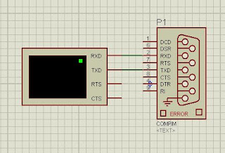
>>If you want to just try it out then no need to create proteus circuit. Just connect one virtual terminal with                                  compim as shown in below figure.

compim connection
compim with terminal

>>Now open properties of compim. In it select physical port, physical baud rate & virtual baud rate.


>>Now get virtual serial port driver & install it in your system.
>>Then run this tool & create a virtal ports pair.

Virtual comport connector
virtual comport connector

>>Then open any terminal client. Open the paired port in virtual serial port driver.


>>That's it. Now your proteus Tx Rx & windows Tx Rx are cross connected.
>>If you have any doubts about this tutorial then feel free to comment.

Proteus virtual port driver
proteus virtual terminal
Download link : 

Posted by :
Read more ...

April 07, 2012

varying scr firing angle with Avr microcontroller(Proteus simulation)

        Hi friends here is the post about changing SCR firing angle control with the help of AVR microcontroller.
        You might be aware of basics of firing angle and its variation.So in a basic Firing angle variation mechanism you will need two things:  
                                                           1)ZERO CROSSING DETECTION  
                                                           2)FIRING SCR  AT DIFFERENT ANGLE
          First stage Zero crossing with AVR is damn easy thing as avr hardware supports zero-crossing detection. that means you can detect zero of 230 VAC with directly avr microcontroller and no additional hardware.
you can refer Avr's official application note to know more about zero crossing by microcontroller itself!!!! (Huh!!!!  QUESTION: How can avr tolerate 230 volts directly?
Answer: 1M resistor limits the current and internal avr diodes are used like clamper circuit.... to convert 230 volts to 5 volts that is accessible by micro-controller.)


zero crossing detection and firing angle control with avr
Zero crossing in avr with internal diodes
             now once you are through with 230v detection and generating an interrupt with the help of zero crossing, you are good to go for varying firing angle of scr.


After varying the firing angle you will be able to see the pulses as shown below


proteus scr firing angle
Firing angle


here is the source code to generate scr triggering pulse from microcontroller and varying it with 2 push buttons(i.e. increase or decrease firing angle) push buttons are connected to  PINA.6 and PINA.7 additionally a stop button is also used to stop SCR firing..
Stop button is connected to PINA.3 Here is the source code for that --------------------------------------------------------------------------------------------
#include"avr/io.h"
#include"delay.h" 
unsigned char stop=0;
unsigned long scrangle=0;
ISR(INT0_vect)
{
if (stop==0)
        {
        delayus(scrangle);
        PORTB=PORTB|0x01;
        delayus(1000);
        PORTB=PORTB &0xFE;
        }
}  void main()
   
     SREG=SREG|0x80;        //global interrupt enable  
     PORTA=0xFF;            // configuering the PORTA in pullup mode.
     DDRA=0x00;                // Port A data direction configuration as input port. 
    MCUCR=MCUCR|0x01;        // logic change  in pin generates an interrupt(hardware interrupt 0) 
    GICR=GICR|0x40;            //enable the interrupt 0 
        if((PINA & 0x80)==0x00)  //decrease firing angle
        {
            if(scrangle>0)
            {
                scrangle=scrangle-100;
            }
        }
        if ((PINA & 0x40)==0x00)    //increase firing angle
         {
            if(scrangle<8000)
            {
                scrangle=scrangle+100;
            }
           
         }
        if((PINA & 0x08)==0x00)    //reset pin to stop
            {
            stop=1;
            }
     } 
} 
 ------------------------------------------------------------------------------------------------------
Here is the output waveforms you can see a pulse generated by micro-controller on zero-crossing detection..

zero crossing with micro-controller
Pulse generated by Micro-controller on zero-crossing.


Thats all I have to say.
But remember some points guys...

1)You are playing with Mains power supply so be very very careful.
2)Ground of microcontroller and mains are not good isolated.
3)This is only pulse generation by microcontroller if you need to apply this pulse to SCR you have to put some conditioning circuit.
Read more ...

March 28, 2012

Power inverter PWM control with AVR (Proteus simulations)

           HI friends here is the post of how to control Power inverter With PWM technique and PWM is generated from Microcontroller.


            Hope that you have read my earlier post about power inverter design that design was traditional design and every thing was done on analog basis like generating triangular waves, comparing with DC offset via a comparator and finally generating PWM.
         
            It is advisable to read first about triggering a single mosfet with microcontroller than going for a full bridge.

           But suddenly you realize that you are living in modern era where microcontrollers can do a lot of things. I also found in built PWM generator mode of AVR microcontroller and reduced a lot of hardware.

           So what I did is configured AVR microcontroller in fast PWM mode and generated all the gate pulses from microcontroller itself.

mosfet inverter with microcontroller pwm control
Triggering mosfets with avre for inverter design
               Here is the Proteus circuit for inverter design.


     One thing to remember here is AS I HAVE SHOWN SEPARATE POWER  SUPPLIES FOR ALL OPTO-COUPLERS YOU HAVE TO USE THEM IN ACTUAL CIRCUIT ALSO OTHERWISE THE INVERTER WILL NOT WORK PROPERLY.

     And one more thing to remember when actually designing inverter from this circuit is that in Proteus you have a common ground but in actual life Ground Concept is  a bit difficult.. so you have to connect ground of respective power supply to source of respected MOSFET.(because we always have to supply Gate pulse with respect to source)


         you can download proteus isis simulation file from HERE.


Correction:
those who have seen circuit before please note the value of resistors r4,r5,r10,r9  there was a typo the value is 220 ohms instead of 560 ohms written before.
           
Read more ...

March 11, 2012

IRF 640 & IRF Z44 triggering with AVR Microcontroller(Proteus Simulation)

I am working with power inverter design for final year project. I am using AVR atmega 8535 microcontroller for triggering MOSFET and PWM control.

I started working with IRF 640 Mosfet (That was the only available to nearer electronics shop at that time).

An optocoupler IC MCT2E is used for isolation between low voltage side(Microcontroller) to the high voltage side (MOSFET side load). It is always suggested to do so.

Here is the circuit configuration i have used to trigger MOSFET. 
optocoupler irf640 triggering with power mosfet
Power mosfet trigger with avr microcontroller by optocoupler in proteus

But while working with optocoupler it is always desirable to use datasheet very carefully. That was the problem with my earlier configuration I blindly put 330 ohm to input side of optocoupler (obviously for current limiting) as we do with normal LED. so I was having 100 uS delay on output side. But that was not proper configuration  according to the MCT2E datasheet. So after studying datasheet and test circuit given in it i come to know that it is 47 ohm is perfect value. And I was able to reduce the delay upto 5 uS(that was desirable to our case).


Then after some successful experiments I replaced IRF 640 with IRF Z44 which was having higher current carrying capacity than the IRF 640.There would be no change in driving circuit as the both MOSFET are pin to pin compatible and gate pulse requirement for both of them is same.

I have tested the circuit in simulations and hardware.

here is the Proteus ISIS simulation of MOSFET triggering 

 
Read more ...
Related Posts Plugin for WordPress, Blogger...